7.9 DESIGN OF CONTROL PILOT VALVES
The main function of a pilot valve is to control a fluid which in turn is used to control or
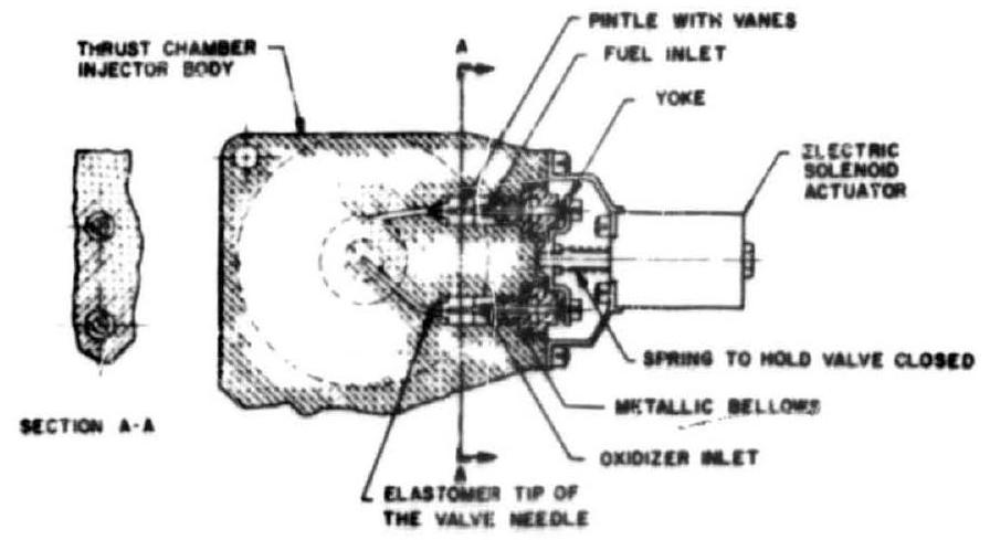 Figure 7-43.-Typical needle-type propellant valve design.
actuate other fluid-flow-control components, such as propellant valves, or to control engine sequence events, such as the admission of igniter fuel. There is a great variety of control pilot valves available for liquid propellant rocket engine services. Basically, they can be grouped into two categories: the on-off type and the proportional type. We confine our discussion here to the on-off type. Since the proportional-type pilot valves are used widely in closed-loop cortrol systems, they will be treated as regulating devices, and discussed in section 7.11. Proportional-type pilot valves are also known as servo valves.
A pilot valve may be operated electrically or by fluid pressure, or through a mechanical connection with other control components. Important design considerations for pilot valves are: (1) Fast response (2) No leakage of control fluid through the valve when closed (3) Requised actuating power source compatible with systems design (4) Sufficient output at the design point
The output of a pilot valve can be defined as
where
valve control fluid discharge pressure at the design point, psig valve volumetric flow rate at the design point, The most frequently used on-off pilot valves may be classified according to their design configurations into (1) Two-way types (2) Three-way types (3) Four-way types
Two-Way-Type Pilot Valves
The term "two-way" refers to the number of porta. A two-way pilot valve is basically a twoport, open-close-type shutoff velve, similar to a propellant valve. The sequence valves shown in figures 7-35 and 7-40 are typical examples of two-way-type pilot valves. Both examples use a mechanical link, actuated from the main valves.
Solenoid or fluid pressure operated tws-way pilot valves are also frequently used.
Three-Way-Type Pilot Valves
A three-way pilot valve (fig. 7-44) has three ports: inlet or pressure port, outiet or cylinder (actuator) port, and vent or return port. If the valve is designed normally closed (N.C.), the fluid path between pressure and cylinder ports is closed, while the path between cylinder and return ports is open. Actuation of the valve effects closing of one fluid path and opening of the other. The reverse is true for a normally open (N.O.) valve; i.e., the fluid path between pressure and cylinder ports is normally open.
Most of the standard pilot valves furnished by specializing manufacturers are solenoid valves, actuated by electrical energy. A direct-acting solenoid valve (fig. 7-44) is one in which opening and closing is controlled by solenoid only. A pilot-operated solenoid valve (fig. 7-45) is one in which the solenoid controls the flow of a small portion of the pressure fluid, which in turn operates the valve. This results in a smaller electrical current required to operate a smaller solenoid for a high-capacity valve. The pilotoperated solenoid valve, necessarily, requires a certain minimum actuating fluid pressure to overcome friction and spring loads before it will open or close.
Figure 7.44 presents a typical direct-acting solenoid, three-way normally closed pilot valve
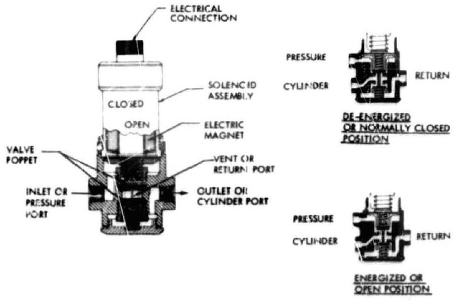 Figure 7-44.-Typical direct-acting solenoid three-way normally closed pilot valve developed by General Controls.
developed by General Controls. Figure 7-45 shows a typical design of a pilot-operated solenoid, three-way pilot valve developed by Skinner. It uses a solenoid to control fluid flow to a diaphragm which opens or cioses the valve. The valve may be normally closed or normally open. The selection of standard pilot valves is based on the design data furnished by their manufacturer. For specific applications, modifications can be incorporated into standard designs.
A typical fluid-pressure-actuated, three-way pilot valve design is shown in figure 7-46. This valve may be used as the ignition monitor valve in the A-1 stage engine control system. The valve is held normally closed by a spring. The valve diaphragm is designed as a combined sensing and actuating diaphragm. During engine start and when satisfactory main thrust chamber ignition has been achieved, the pressure bu ldup sensed at the thrust chamber injector fuel manifold will cause the ignition monitor valve to open
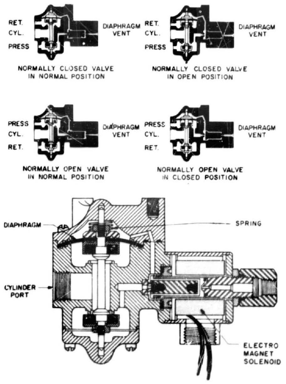 Figure 7-45.-Typical aesign of a pilot-operated solenoid, three-way pilot valve developed by Skinner.
by pressurizing its diaphragm. The opening of the ignition monitor valve, in turn, directs the fuel pressure to the main fuel valve actuator opening port. The valve spring can be calibrated corresponding to the effective diaphragm area, so that the valve will open at a predetermined sensed pressure. During engine cutoff, decreasing fuel pressure allows the ignition monitor valve to close. This, in turn, vents the opening side of the main fuel valve actuator, closing the valve.
The valve poppet is balanced by internal fluid pressure acting on a dynamic O-ring seal which has the same diameter as the poppet. The valve diaphragm is made of multilayer, thin ( 0.01 inch) Mylar sheets which are pressure formed with heat added. The effective diaphragm area can be determined experimentally. The required preload of the valve sping may then be estimated by
where effective diaphragm diameter, in rated sensed threshold pressure to open the valve, psig static friction of the valve poppet, lb required preioad of the valve spring, lb
Sample Calculation (7-4)
The following design data are given for the ignition monitor valve of the A-1 stage engine (fig. 7-46):
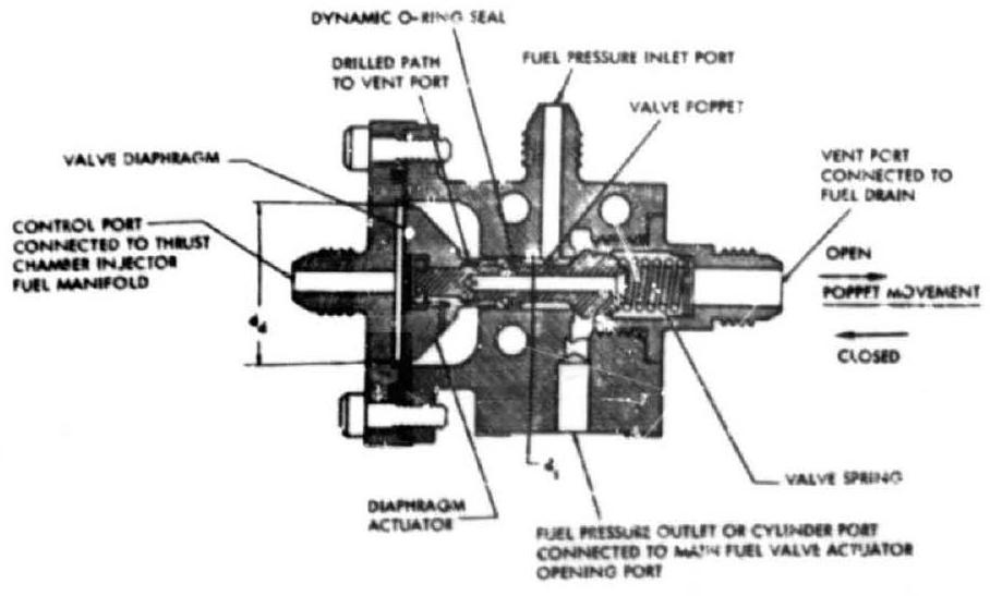 Figure 7-46.-Typical fluid pressure actuated three-way piloi valve used as the ignition monitor valve in the A-1 stage engine.
Valve characteristic flow area in the fully open position, ; Valve resistance coefficient at the fully open position, Required valve volumetric flow rate, Inlet port fuel pressure Determine the required preload of the valve spring, . Also, calculate the valve output in the fully open position.
Solution
From equation (7-18), the required valve spring preload
The characteristic flow velocity of the valve
The density of the fuel ( ) is . Substitute this and other data into equation (79). The pressure drop through the valve at the design point
The fuel pressure at the valve discharge
Substitute into equation (7-17), the valve output
Four-Way Type Rilot Valves
A four-way-type pilot valve can replace two three-way valves, for control of double-acting (two-directional) actuators, as shown in figures 7-33 and 7-40. Figure 7-47 presents the basic schematic of a four-way pilot valve. The ports are arranged so that one side is venting while the other is pressurizing.
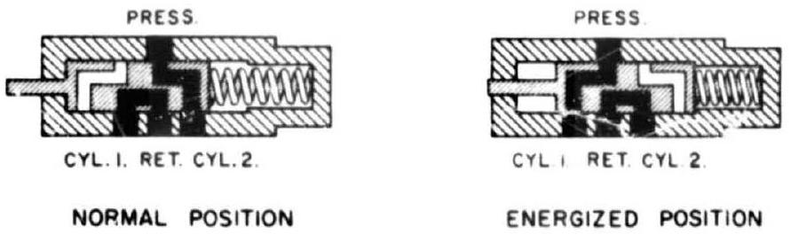 Figure 7-47.-Basic schematic of a four-way pilot valve.
The typical design of a pilot-operated fourway solenoid pilot valve, developed by Valvair, is shown in figure 7-48. This valve type is used to control pneumatic actuators.
Figure 7-49 presents the schematic of a typical self-locking-type, four-way pilot valve. It is held normally closed (cylinder 1 port) by springs and . When an actuating pressure is applied to the opening port, the pintle moves and connects the pressure port to cylinder 1 port, and cylinder 2 port to the return port. An unbalanced self-locking force, , acting in the opening direction, causes the valve to stay cpen, even after the actuating pressure is removed from the opening port. The valve can be closed only by pressurizing the closing port, and venting the opening port.
Sample Calculation (7-5)
The following data are given for the self-locking-type, four-way pilot valve shown in figure 7-49. spring: Preload , rate spring: Preload , rate Static friction of the valve poppet, Pressure port pressure, Actuating fluid pressure, Return port pressure ambient Poppet guide diameter, Valve poppet total travel in Determine diameters , and (using an actuating-force contingency factor of 1.5).
Solution
Calculate diaphragm diameter for the required actuating force to open the valve:
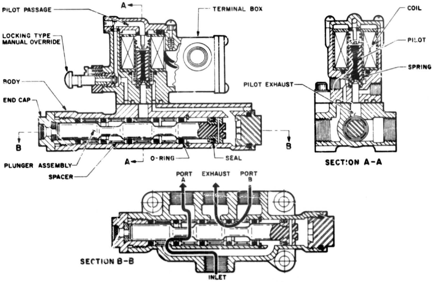 Figure 7-48.-Typical design of a pilot-operated, four-way solenoid pilot valve, developed by Valvair.
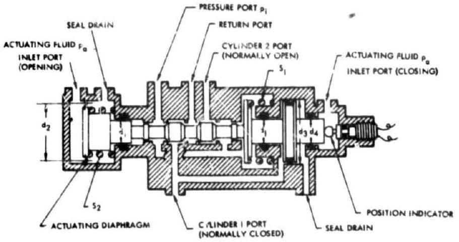 Figure 7-49.-Schematic of a typical self-lockingtype, four-way pilot valve.
Determine piston diameter , based on the required force to lock the valve in the open position, in the event the actuating pressure is lost:
Calculate diameter for the required force to close the valve:
Design of Solenoid Actuators
Solenoid actuators are usually applied to the sliding stem of pilot valve poppets, for on-off, two-position operation (figs. 7-44, 7-45, and 7-48). Solenoids are electromagnets, containing an armature or plunger which moves in a coil of wire. When the coil is energized, a magnetic force is exerted on the plunger. The magnitude of the force is proportional to the cross-sectional area of the plunger, the number of the coil turns, the electric current applied to the coil, and the gap between plunger and core. It increases as the gap narrows.
Figure 7-50 shows a typical direct-current solenoid actuator as frequently used in two-position-type, pilot valve services. Its ma,gnetic current consists of a stationary core, the case, a base, and the plunger. When the coil is energized, the plunger, along with the valve stem connected to it by a bolt, is pulled toward the core, against a compression spring. This spring pushes the plunger back to the normal position when the coil is deenergized.
The following are general correlations for flat-faced, plunger-type magnets of the type shown in figure 7-50.
where
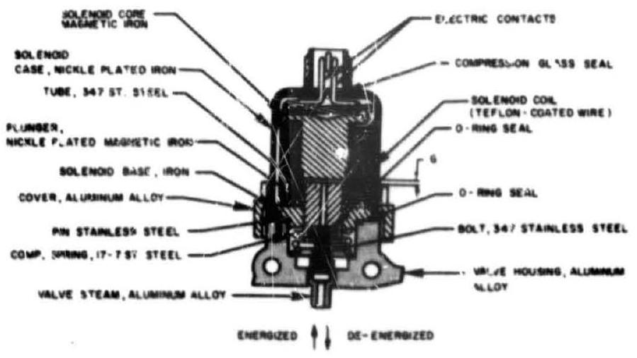 Figure 7-50.-Typical direct-current solenoid actuator design frequently used in two-positiontype pilot valves.
magnetic flux density in the air gap, kilomaxwells/in plunger cross-sectional area, factor comprising constants and allowances for stray flux. A value of 72 is applicable to round, flat-faced, plungertype magnets factor comprising constants and the permeability of the fluid in gap between core and plunger; a value of 0.00319 applies if an airgap is assumed flux leakage factor. It is determined by analyzing the magnetic circuit number of coil turns electric current applied to the coil, amperes gap between core and plunger, in Solenoid actuators, particularly if energized for extended periods, must be designed with sufficient radiating surface to prevent the temperature from becoming excessive. To give the required current, the resistance of the coil should be based on its maximum temperature. Suitable protection, such as seals, should be provided to prevent the solenoid from becoming contaminated with propellants. If the plunger is designed to bottom-out against the core when energized, it is advisable to provide for a thin wafer of nonmagnetic material at its face to prevent sticking.
Sample Calculation (7-6)
The following data are given for the solenoid actuator of the A-2 stage engine four-way pilot control valve:
Required actuating force at start of stroke, Nominal electric supply: 28 volts dc: 2.0 amperes maximum Valve poppet travel = Air gap between solenoid core and plunger, in Plunger diameter Assumed flux leakage factor, Determine the amphere-turn requirements of the solenoid.
Solution
Plunger area:
Substitute this and other values into equation (7-19):
The required flux density: kilomaxwells Substitute this into equation (7-20):
The required ampere-turns for the solenoid coil
Assume a current of 1.4 amperes for the solenoid; then the required number of turns
The required electric resistance of the solenoid coil, at operating temperature
The wire can now be selected for the required resistance. For instance, we may choose a No. 26 AWG copper wire ( 0.017 -inch diameter, enameled) and wind it to an average coil diameter of 1.05 inches.
Resistance , warm. Total length . ohms. Lay wires 22 deep, 65 high. Thickness of coil: . Inside diameter . This leaves for insulation, sleeves, and plunger clearance. Height of coil: inches. Outside diameter inches.